Complex MPLS VPN with BGP Protocol between CE-PE
Complex MPLS VPN with BGP Protocol between CE-PE
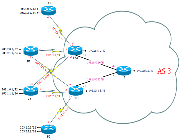
A Complex MPLS (Multiprotocol Label Switching) VPN with BGP (Border Gateway Protocol) protocol between Customer Edge (CE) and Provider Edge (PE) routers constitutes an advanced networking architecture designed to offer secure, scalable, and versatile connectivity across multiple geographically dispersed locations. In this setup, BGP serves as the routing protocol between the CE and PE routers, facilitating the exchange of routing information and VPN-specific attributes. The use of MPLS allows for efficient packet forwarding within the service provider's network, utilizing labels to streamline routing and support traffic engineering. This combination enables the creation of sophisticated virtualized networks, providing isolated communication channels for various customers. The Complex MPLS VPN with BGP protocol between CE-PE routers is an ideal solution for enterprises with diverse networking needs, offering a robust framework for ensuring privacy, reliability, and optimized performance across their distributed infrastructure.
Lab:
Disclaimer
This Configuration Guide is designed to assist members to enhance their skills in particular technology area. While every effort has been made to ensure that all material is as complete and accurate as possible, the enclosed material is presented on an “as is” basis. Neither the authors nor Forum assume any liability or responsibility to any person or entity with respect to loss or damages incurred from the information contained in this guide. This configuration guide was developed by Forum. Any similarities between material presented in this configuration guide and any other material is completely coincidental.
IOS used: c7200-p-mz.120-32.S.bin
Task 1: Basic OSPF and MPLS setup Configure OSPF and MPLS on all PE-routers and P-router
Step 1. Configure following on respective P and PE routers:
PE2 Router Initial Config:
hostname PE2
!
ip cef
mpls label protocol ldp
no tag-switching ip propagate-ttl
!
interface Loopback0
ip address 192.168.3.2 255.255.255.255
!
interface FastEthernet1/0
description **link_to_P**
ip address 192.168.3.18 255.255.255.252
tag-switching ip
no shutdown
!
interface Serial2/0
description **link_to_A2**
ip address 150.1.31.5 255.255.255.252
no shutdown
!
interface Serial2/1
description **link_to_B1**
ip address 150.1.32.1 255.255.255.252
no shutdown
!
interface Serial2/2
description **link_to_A1**
ip address 150.1.31.9 255.255.255.252
no shutdown
!
router ospf 64
log-adjacency-changes
network 192.168.0.0 0.0.255.255 area 0
!
end
PE3 Router Initial Config:
hostname PE3
!
ip cef
mpls label protocol ldp
no tag-switching ip propagate-ttl
!
interface Loopback0
ip address 192.168.3.3 255.255.255.255
!
interface FastEthernet0/0
description **link_to_P**
ip address 192.168.3.13 255.255.255.252
tag-switching ip
no shutdown
!
interface Serial2/0
description **link_to_B1**
ip address 150.1.32.9 255.255.255.252
no shutdown
!
interface Serial2/1
description **link_to_A1**
ip address 150.1.31.1 255.255.255.252
no shutdown
!
interface Serial2/2
description **link_to_B2**
ip address 150.1.32.5 255.255.255.252
no shutdown
!
router ospf 64
log-adjacency-changes
network 192.168.0.0 0.0.255.255 area 0
!
end
P Router Config:
hostname P
!
ip cef
mpls label protocol ldp
no tag-switching ip propagate-ttl
!
interface Loopback0
ip address 192.168.3.5 255.255.255.255
!
interface FastEthernet0/0
description **link_to_PE3**
ip address 192.168.3.14 255.255.255.252
tag-switching ip
no shutdown
!
interface FastEthernet1/0
description **link_to_PE2**
ip address 192.168.3.17 255.255.255.252
tag-switching ip
no shutdown
!
router ospf 64
log-adjacency-changes
network 192.168.0.0 0.0.255.255 area 0
!
end
A2 Router Config:
hostname A2
!
interface Loopback0
ip address 203.1.0.2 255.255.255.255
!
interface Loopback1
ip address 203.1.2.1 255.255.255.0
!
interface Serial2/0
ip address 150.1.31.6 255.255.255.252
clock rate 64000
no shutdown
!
end
B1 Router Initial Config:
hostname B1
!
interface Loopback0
ip address 203.2.0.1 255.255.255.255
!
interface Loopback1
ip address 203.2.1.1 255.255.255.0
!
interface Serial2/0
ip address 150.1.32.10 255.255.255.252
clock rate 64000
no shutdown
!
interface Serial2/1
ip address 150.1.32.2 255.255.255.252
clock rate 64000
no shutdown
!
end
A1 Router Initial Config:
hostname A1
!
interface Loopback0
ip address 203.1.1.1 255.255.255.0
!
interface Loopback1
ip address 203.1.0.1 255.255.255.255
!
interface Serial2/1
ip address 150.1.31.2 255.255.255.252
clock rate 64000
no shutdown
!
interface Serial2/2
ip address 150.1.31.10 255.255.255.252
clock rate 64000
no shutdown
!
end
B1 Router Initial Config:
hostname B2
!
interface Loopback0
ip address 203.2.0.2 255.255.255.255
!
interface Loopback1
ip address 203.2.2.1 255.255.255.0
!
interface Serial2/2
ip address 150.1.32.6 255.255.255.252
clock rate 64000
no shutdown
!
end
Task 2: Configure Multi-protocol BGP between provider-edge (PE) routers.
Step 1: Enable BGP sessions on all PE routers in your Service Provider backbone.
Step 2: Activate VPNv4 BGP sessions between all PE routers in your Service Provider backbone.
Configure the following on PE2 router:
PE2(config)#
router bgp 3
 neighbor 192.168.3.3 remote-as 3
 neighbor 192.168.3.3 update-source Loopback0
 !
 address-family ipv4
 no auto-summary
 no synchronization
 neighbor 192.168.3.3 activate
 network 192.168.3.2 mask 255.255.255.255
 exit-address-family
 !
 address-family vpnv4
 neighbor 192.168.3.3 activate
 neighbor 192.168.3.3 send-community extended
 exit-address-family
Configure following on PE3 router:
router bgp 3
 bgp log-neighbor-changes
 neighbor 192.168.3.2 remote-as 3
 neighbor 192.168.3.2 update-source Loopback0
 !
 address-family ipv4
 no auto-summary
 no synchronization
 neighbor 192.168.3.2 activate
 network 192.168.3.3 mask 255.255.255.255
 exit-address-family
 !
 address-family vpnv4
 neighbor 192.168.3.2 activate
 neighbor 192.168.3.2 send-community extended
 exit-address-family
Task 3: Design your VPN Solution
Create the virtual private network (VRF) on provider edge (PE2)
PE2(config)#
ip vrf a
rd 3:1
 route-target both 3:1
!
ip vrf a_central
 rd 3:11
 route-target both 3:1
 route-target both 3:30
!
ip vrf b_central
 rd 3:21
 route-target both 3:2
 route-target both 3:30
Create the virtual private network (VRF) on provider edge (PE3):
PE3(config)#
ip vrf a_central
rd 3:11
 route-target both 3:1
 route-target both 3:30
!
ip vrf b
 rd 3:2
 route-target both 3:2
!
ip vrf b_central
 rd 3:21
 route-target both 3:2
 route-target both 3:30
Task 4: Create VRFs for A2, B1, A1 and B2
Attach the provider edge-to-customer edge (PE-CE) link to the newly created VRFs with the following commands on PE2:
PE2(config)#
interface Serial2/0
ip vrf forwarding a
 ip address 150.1.31.5 255.255.255.252
!
interface Serial2/1
 ip vrf forwarding b_central
 ip address 150.1.32.1 255.255.255.252
!
interface Serial2/2
 ip vrf forwarding a_central
 ip address 150.1.31.9 255.255.255.252
Note: "ip vrf forwarding name" command removes the IP address from interface, so IP address need to be re-configured.
Attach the PE-CE link to the newly created VRFs with the following commands on PE3:
PE3(config)#
interface Serial2/0
 ip vrf forwarding b_central
 ip address 150.1.32.9 255.255.255.252
!
interface Serial2/1
 ip vrf forwarding a_central
 ip address 150.1.31.1 255.255.255.252
!
interface Serial2/2
 ip vrf forwarding b
 ip address 150.1.32.5 255.255.255.252
Task 5: configure BGP on A1, B1 and A2, B2
The following commands need to be entered on the A1 router:
A1(config)#
router bgp 2
neighbor 150.1.31.1 remote-as 3
neighbor 150.1.31.1 allowas-in
neighbor 150.1.31.9 remote-as 3
neighbor 150.1.31.9 allowas-in
redistribute connected
The following commands need to be entered on the B1 router:
B1(config)#
router bgp 4
neighbor 150.1.32.1 remote-as 3
neighbor 150.1.32.1 allowas-in
neighbor 150.1.32.9 remote-as 3
neighbor 150.1.32.9 allowas-in
redistribute connected
The following commands need to be entered on the A2 router:
A2(config)#
router bgp 2
neighbor 150.1.31.5 remote-as 3
neighbor 150.1.31.5 allowas-in
redistribute connected
The following commands need to be entered on the B2 router:
B2(config)#
router bgp 4
neighbor 150.1.32.5 remote-as 3
neighbor 150.1.32.5 allowas-in
redistribute connected
Task 6: Configure New VRFs For A1 and B1/Re-establish BGP Routing
The following commands need to be entered on PE2:
PE2(config)#
router bgp 3
address-family ipv4 vrf b_central
neighbor 150.1.32.2 remote-as 4
neighbor 150.1.32.2 activate
neighbor 150.1.32.2 as-override
exit
address-family ipv4 vrf a_central
neighbor 150.1.31.10 remote-as 2
neighbor 150.1.31.10 activate
neighbor 150.1.31.10 as-override
exit
address-family ipv4 vrf a
neighbor 150.1.31.6 remote-as 2
neighbor 150.1.31.6 activate
neighbor 150.1.31.6 as-override
exit
The following commands need to be entered on PE3:
PE3(config)#
router bgp 3
address-family ipv4 vrf b_central
neighbor 150.1.32.10 remote-as 4
neighbor 150.1.32.10 activate
neighbor 150.1.32.10 as-override
exit
address-family ipv4 vrf b
neighbor 150.1.32.6 remote-as 4
neighbor 150.1.32.6 activate
neighbor 150.1.32.6 as-override
exit
address-family ipv4 vrf a_central
neighbor 150.1.31.2 remote-as 2
neighbor 150.1.31.2 activate
neighbor 150.1.31.2 as-override
exit