Loading...
DMVPN - Border Gateway Protocol (BGP)
DMVPN BGP
Dynamic Multipoint Virtual Private Network (DMVPN) with Border Gateway Protocol (BGP) is a network architecture that combines the benefits of DMVPN and BGP to provide scalable and efficient communication across a network. In a DMVPN BGP deployment, BGP is used as the routing protocol to dynamically exchange routing information between DMVPN spokes and hub, allowing for optimal routing in a hub-and-spoke topology. This approach enhances the scalability of DMVPN by leveraging the BGP's ability to handle large-scale networks and provide efficient route summarization. BGP in DMVPN also enables the dynamic establishment of tunnels between spokes, eliminating the need for a full mesh configuration and simplifying the network architecture. DMVPN BGP is commonly used in scenarios where a large number of remote sites need to connect securely and efficiently, making it a flexible and scalable solution for modern enterprise networks.
Lab:
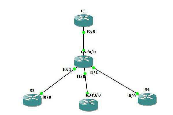
DMVPN Topology
Task 1: Configure BGP over DMVPN Process
Step 1: In the configuration mode of router configure BGP over DMVPN by following command:
R1:
router ospf 1
network 0.0.0.0 0.0.0.0 area 0
exit

int tunnel 0
ip ospf network broadcast
ip ospf priority 255
exit

router bgp 65000
neighbor 192.168.0.2 remote-as 65000
neighbor 192.168.0.2 soft-reconfiguration inbound
neighbor 192.168.0.3 remote-as 65000
neighbor 192.168.0.3 soft-reconfiguration inbound
neighbor 192.168.0.4 remote-as 65000
neighbor 192.168.0.4 soft-reconfiguration inbound
address-family ipv4
network 11.0.0.0 mask 255.0.0.0
exit
R2:
router ospf 1
network 0.0.0.0 0.0.0.0 area 0
exit

interface tunnel 0
ip ospf network broadcast
ip ospf priority 0
exit

router bgp 65000
neighbor 192.168.0.1 remote-as 65000
neighbor 192.168.0.1 soft-reconfiguration inbound
address-family ipv4
network 22.0.0.0 mask 255.0.0.0
exit
R3:
router ospf 1
network 0.0.0.0 0.0.0.0 area 0
exit

interface tunnel 0
ip ospf network broadcast
ip ospf priority 0
exit

router bgp 65000
neighbor 192.168.0.1 remote-as 65000
neighbor 192.168.0.1 soft-reconfiguration inbound
address-family ipv4
network 33.0.0.0 mask 255.0.0.0
exit
R4:
router ospf 1
network 0.0.0.0 0.0.0.0 area 0
exit

interface tunnel 0
ip ospf network broadcast
ip ospf priority 0
exit

router bgp 65000
neighbor 192.168.0.1 remote-as 65000
neighbor 192.168.0.1 soft-reconfiguration inbound
address-family ipv4
network 44.0.0.0 mask 255.0.0.0
exit
Task 2: BGP over DMVPN Verification
Step 1: Verify BGP Table
R1#show ip bgp
BGP table version is 8, local router ID is 11.11.11.11
Status codes: s suppressed, d damped, h history, * valid, > best, i - internal,
 r RIB-failure, S Stale
Origin codes: i - IGP, e - EGP, ? - incomplete

 Network          Next Hop     Metric    LocPrf    Weight    Path
*> 11.11.11.0/24  0.0.0.0       0        32768               i
 >i22.22.22.0/24  192.168.0.2   0        100                  0 i
 >i33.33.33.0/24  192.168.0.3   0        100                  0 i
 >i44.44.44.0/24  192.168.0.4   0        100                  0 i
R2#show ip bgp
BGP table version is 4, local router ID is 22.22.22.22
Status codes: s suppressed, d damped, h history, * valid, > best, i - internal,
Origin codes: i - IGP, e - EGP, ? - incomplete

 Network           Next Hop      Metric      LocPrf      Weight      Path
 >i11.11.11.0/24   192.168.0.1   0           100         0           i
*> 22.22.22.0/24   0.0.0.0       0           32768                   i
R3#show ip bgp
BGP table version is 4, local router ID is 33.33.33.33
Status codes: s suppressed, d damped, h history, * valid, > best, i - internal,
Origin codes: i - IGP, e - EGP, ? - incomplete

 Network          Next Hop       Metric      LocPrf      Weight       Path
 >i11.11.11.0/24  192.168.0.1    0           100         0            i
*> 33.33.33.0/24  0.0.0.0        0           32768                    i
R4#show ip bgp
BGP table version is 4, local router ID is 44.44.44.44
Status codes: s suppressed, d damped, h history, * valid, > best, i - internal,
Origin codes: i - IGP, e - EGP, ? - incomplete

 Network          Next Hop       Metric      LocPrf       Weight      Path
 >i11.11.11.0/24  192.168.0.1    0           100          0           i
*> 44.44.44.0/24  0.0.0.0        0           32768                    i
Split Horizon doesn't allows spoke to forward BGP Routes to other spokes, because rule is Routes received from one IBGP neighbor is not forwarded to other IBGP neighbor.
Step 2: Configure BGP Route Reflector
R1:
router bgp 65000
neighbor 192.168.0.2 remote-as 1
neighbor 192.168.0.2 route-reflector-client
neighbor 192.168.0.4 remote-as 1
neighbor 192.168.0.4 route-reflector-client
exit
R1#show ip bgp
BGP table version is 8, local router ID is 11.11.11.11
Status codes: s suppressed, d damped, h history, * valid, > best, i - internal,
 r RIB-failure, S Stale
Origin codes: i - IGP, e - EGP, ? - incomplete

 Network           Next Hop      Metric     LocPrf     Weight    Path
*> 11.11.11.0/24   0.0.0.0       0          32768                i
 >i22.22.22.0/24   192.168.0.2   0          100                  0 i
 >i33.33.33.0/24   192.168.0.3   0          100                  0 i
 >i44.44.44.0/24   192.168.0.4   0          100                  0 i
R2#show ip bgp
BGP table version is 14, local router ID is 22.22.22.22
Status codes: s suppressed, d damped, h history, * valid, > best, i - internal,
 r RIB-failure, S Stale
Origin codes: i - IGP, e - EGP, ? - incomplete

 Network          Next Hop       Metric      LocPrf      Weight       Path
 >i11.11.11.0/24  192.168.0.1    0           100         0            i
*> 22.22.22.0/24  0.0.0.0        0           32768       0            i
 >i33.33.33.0/24  192.168.0.3    0           100         0            i
 >i44.44.44.0/24  192.168.0.4    0           100         0            i
R3#show ip bgp
BGP table version is 8, local router ID is 33.33.33.33
Status codes: s suppressed, d damped, h history, * valid, > best, i - internal,
 r RIB-failure, S Stale
Origin codes: i - IGP, e - EGP, ? - incomplete

 Network          Next Hop      Metric      LocPrf       Weight    Path
 >i11.11.11.0/24 192.168.0.1    0           100          0         i
 >i22.22.22.0/24 192.168.0.2    0           100          0         i
*> 33.33.33.0/24 0.0.0.0        0           32768                  i
 >i44.44.44.0/24 192.168.0.4    0           100          0         i
R4#show ip bgp
BGP table version is 14, local router ID is 44.44.44.44
Status codes: s suppressed, d damped, h history, * valid, > best, i - internal,
 r RIB-failure, S Stale
Origin codes: i - IGP, e - EGP, ? - incomplete

 Network           Next Hop        Metric       LocPrf       Weight       Path
 >i11.11.11.0/24   192.168.0.1     0            100          0            i
 >i22.22.22.0/24   192.168.0.2     0            100          0            i
 >i33.33.33.0/24   192.168.0.3     0            100          0            i
*> 44.44.44.0/24   0.0.0.0         0            32768                     i
Step 1: Verify DMVPN Tunnel creation
R1#show dmvpn
Legend: Attrb --> S - Static, D - Dynamic, I - Incomplete
   N - NATed, L - Local, X - No Socket
   # Ent --> Number of NHRP entries with same NBMA peer
   NHS Status: E --> Expecting Replies, R --> Responding
   UpDn Time --> Up or Down Time for a Tunnel

================================================================

Interface: Tunnel0, IPv4 NHRP Details
Type:Hub, NHRP Peers:3,

 # Ent Peer NBMA Addr Peer Tunnel Add State UpDn Tm Attrb
----- --------------- --------------- ----- -------- -----
 1 172.16.2.2 192.168.0.2 UP 01:35:07 D
 1 172.16.3.2 192.168.0.3 UP 01:35:01 D
 1 172.16.4.2 192.168.0.4 UP 01:35:02 D
R2#show dmvpn
Legend: Attrb --> S - Static, D - Dynamic, I - Incomplete
 N - NATed, L - Local, X - No Socket
 # Ent --> Number of NHRP entries with same NBMA peer
 NHS Status: E --> Expecting Replies, R --> Responding
 UpDn Time --> Up or Down Time for a Tunnel
=======================================================================
Interface: Tunnel0, IPv4 NHRP Details
Type:Spoke, NHRP Peers:3,
 # Ent Peer NBMA Addr Peer Tunnel Add State UpDn Tm Attrb
----- --------------- --------------- ----- -------- -----
 1 172.16.1.2 192.168.0.1 UP 00:55:53 S
R2#ping 192.168.0.3
Type escape sequence to abort.
Sending 5, 100-byte ICMP Echos to 192.168.0.3, timeout is 2 seconds:
!!!!!
Success rate is 100 percent (5/5), round-trip min/avg/max = 196/261/340 ms
R2#show dmvpn
Legend: Attrb --> S - Static, D - Dynamic, I - Incomplete
 N - NATed, L - Local, X - No Socket
 # Ent --> Number of NHRP entries with same NBMA peer
 NHS Status: E --> Expecting Replies, R --> Responding
 UpDn Time --> Up or Down Time for a Tunnel
=======================================================================
Interface: Tunnel0, IPv4 NHRP Details
Type:Spoke, NHRP Peers:3,
 # Ent Peer NBMA Addr Peer Tunnel Add State UpDn Tm Attrb
----- --------------- --------------- ----- -------- -----
 1 172.16.1.2 192.168.0.1 UP 00:57:01 S
 1 172.16.3.2 192.168.0.3 UP 00:51:50 D
Notice that the tunnel to R4 has been flagged as dynamic, in contrast to the static tunnel to the hub/NHS.
R2# ping 192.168.0.4
Type escape sequence to abort.
Sending 5, 100-byte ICMP Echos to 192.168.0.4, timeout is 2 seconds:
!!!!!
Success rate is 100 percent (5/5), round-trip min/avg/max = 156/189/220 ms
R2#traceroute 192.168.0.4 source loopback 1
Type escape sequence to abort.
Tracing the route to 192.168.0.4

1 192.168.0.4 396 msec 508 msec
Once the dynamically tunnel is formed between spoke to spoke router, DMVPN allows to Spoke to Spoke directly communication at next hop thus bypassing the Hub router completely
R2#show dmvpn
Legend: Attrb --> S - Static, D - Dynamic, I - Incomplete
 N - NATed, L - Local, X - No Socket
 # Ent --> Number of NHRP entries with same NBMA peer
 NHS Status: E --> Expecting Replies, R --> Responding
 UpDn Time --> Up or Down Time for a Tunnel
=======================================================================
Interface: Tunnel0, IPv4 NHRP Details
Type:Spoke, NHRP Peers:3,
 # Ent Peer NBMA Addr Peer Tunnel Add State UpDn Tm Attrb
----- --------------- --------------- ----- -------- -----
 1 172.16.1.2 192.168.0.1 UP 00:58:55 S
 1 172.16.3.2 192.168.0.3 UP 00:53:43 D
 1 172.16.4.2 192.168.0.4 UP 00:56:37 D
R3#show dmvpn
Legend: Attrb --> S - Static, D - Dynamic, I - Incomplete
 N - NATed, L - Local, X - No Socket
 # Ent --> Number of NHRP entries with same NBMA peer
 NHS Status: E --> Expecting Replies, R --> Responding
 UpDn Time --> Up or Down Time for a Tunnel
=======================================================================
Interface: Tunnel0, IPv4 NHRP Details
Type:Spoke, NHRP Peers:3,
 # Ent Peer NBMA Addr Peer Tunnel Add State UpDn Tm Attrb
----- --------------- --------------- ----- -------- -----
 1 172.16.1.2 192.168.0.1 UP 01:00:16 S
 1 172.16.2.2 192.168.0.2 UP 00:55:20 D
 1 172.16.4.2 192.168.0.4 UP 00:00:03 D
R4#sh dmvpn
Legend: Attrb --> S - Static, D - Dynamic, I - Incomplete
 N - NATed, L - Local, X - No Socket
 # Ent --> Number of NHRP entries with same NBMA peer
 NHS Status: E --> Expecting Replies, R --> Responding
 UpDn Time --> Up or Down Time for a Tunnel
========================================================================
Interface: Tunnel0, IPv4 NHRP Details
Type:Spoke, NHRP Peers:3,
 # Ent Peer NBMA Addr Peer Tunnel Add State UpDn Tm Attrb
----- --------------- --------------- ----- -------- -----
 1 172.16.1.2 192.168.0.1 UP 01:00:41 S
 1 172.16.2.2 192.168.0.2 UP 00:58:41 D
 1 172.16.3.2 192.168.0.3 UP 00:00:31
DMVPN Tunnel from one to spoke to every other spoke is dynamically formed thus direct communication from spoke to spoke is possible
Brilliance of DMVPN lies in its ability to dynamically establish spoke-to-spoke tunnels. In a legacy hub and spoke design, a packet destined from R2 to R4 would need to be routed through R1, to exit the R2 tunnel and the get re-encapsulated to enter the R4 tunnel. Clearly a better path lies directly via R5, and DMVPN allows us to take advantage of this. Packet capture of traffic from R2 to R4. Traffic initially follows the path through R1 as described above, while a dynamic tunnel is built from R2 to R4 using NHRP. After the new tunnel has been established, traffic flows across it, bypassing R1 completely.