Loading...
DMVPN - Initial Configuration
Initial Configuration
Dynamic Multipoint Virtual Private Network (DMVPN) Initial Configuration involves setting up the necessary parameters and components to establish a secure and scalable network infrastructure. In a typical DMVPN initial configuration, the hub router is configured with the necessary DMVPN parameters, including the creation of Virtual Tunnel Interfaces (VTIs) and the assignment of IP addresses. Spoke routers are configured with the appropriate DMVPN parameters to establish secure connections with the hub. Additionally, routing protocols, such as EIGRP, OSPF, or BGP, may be configured to facilitate dynamic routing between the DMVPN spokes and the hub. Security features like IPsec are often employed to encrypt and protect the data transmitted over the DMVPN. The initial DMVPN configuration ensures that the network is ready for scalable and efficient communication, making it a versatile solution for connecting multiple remote sites securely over the Internet.
Lab:
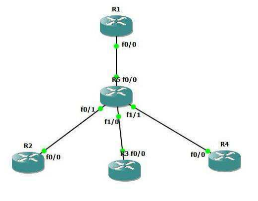
DMVPN Topology
Task 1: Configure DMVPN Initial Configuration
Step 1: In the configuration mode of router configure by following command: command:
R1:
interface FastEthernet0/0                          //creating Active interface
ip address 172.16.1.2 255.255.255.252              //Physical/Public/NBMA Address provided by ISP
no shutdown

interface loopback 1
ip address 11.11.11.11 255.255.255.0
exit

interface Tunnel 0                                   //creating Virtual interface
ip address 192.168.0.1 255.255.255.0                //Overlay/Private/admin define IP address
exit

ip route 0.0.0.0 0.0.0.0 172.16.1.1                 //static routes pointing toward Internet simulated router
R2:
interface FastEthernet0/0
ip address 172.16.2.2 255.255.255.252
no shutdown

interface Tunnel 0
ip address 192.168.0.2 255.255.255.0
exit

ip route 0.0.0.0 0.0.0.0 172.16.2.1

interface loopback 1
ip address 22.22.22.22 255.255.255.0
exit
R3:
interface FastEthernet0/0
ip address 172.16.3.2 255.255.255.252
no shutdown

interface Tunnel 0
ip address 192.168.0.3 255.255.255.0
exit
ip route 0.0.0.0 0.0.0.0 172.16.3.1

interface loopback 1
ip address 33.33.33.33 255.255.255.0
exi
R4:
interface FastEthernet0/0
ip address 172.16.4.2 255.255.255.252
no shutdown

interface Tunnel 0
ip address 192.168.0.4 255.255.255.0
exit

ip route 0.0.0.0 0.0.0.0 172.16.4.1

interface loop 1
ip address 44.44.44.44 255.255.255.0
exit
Step 2: Configuring DMVP Process
R1:
interface tunnel 0              //entering virtual interface tunnel 0
ip nhrp map multicast dynamic  //enables forwarding of multicast traffic across the tunnel to dynamic spokes required by most routing protocols

ip nhrp network-id 5                                           //uniquely identifies the DMVPN network; tunnels will not form
                                                               between routers with differing network IDs
tunnel source 172.16.1.2                                       //exit interface or NBMA address of exit interface
tunnel mode gre multipoint                                     //GRE mode multipoint
ip mtu 1400                                                    //tunning MTU because of DMVPN header
exit
Here tunnel does not have an explicit destination specified because multipoint tunnels are built dynamically from the spokes to the hub router; the huď router doesŶ’t Ŷeed to be preconfigured with spoke addresses.
R2:
interface tunnel 0                          //entering virtual interface tunnel 0
ip nhrp network-id 5                        //nhrp network ID
tunnel source 172.16.2.2                    //exit interface or NBMA address of exit interface
ip nhrp map 192.168.0.1 172.16.1.2          //statiĐally ŵaps the NHS address to R1’s physiĐal address
ip nhrp map multicast 172.16.1.2            //multicast traffic is only allowed from spokes to the hub, not from spoke to spoke

ip nhrp nhs 192.168.0.1                     // ip nhrp nhs 192.168.0.1 designates R1 as the Next Hop Server
tunnel mode gre multipoint                  //GRE mode multipoint
ip mtu 1400                                 //tunning MTU because of DMVPN header
exit
R3:
int tunnel 0
ip nhrp network-id 5
tunnel source 172.16.3.2
ip nhrp map 192.168.0.1 172.16.1.2
ip nhrp map multicast 172.16.1.2
ip nhrp nhs 192.168.0.1
ip mtu 1400
tunnel mode gre multipoint
exit
R4:
int tunnel 0
ip nhrp network-id 5
tunnel source 172.16.4.2
ip nhrp map 192.168.0.1 172.16.1.2
ip mtu 1400
ip nhrp map multicast 172.16.1.2
ip nhrp nhs 192.168.0.1
tunnel mode gre multipoint
exit
Task 2: DMVPN Verification
Step 2: Verify DMVPN Tunnel creation
R1:
R1#show dmvpn
//shows detailts of dmvpn tunnel

Legend: Attrb --> S - Static, D - Dynamic, I - Incomplete
 N - NATed, L - Local, X - No Socket
 # Ent --> Number of NHRP entries with same NBMA peer
 NHS Status: E --> Expecting Replies, R --> Responding
 UpDn Time --> Up or Down Time for a Tunnel
=======================================================================

Interface: Tunnel0, IPv4 NHRP Details
Type:Hub, NHRP Peers:3,

 # Ent Peer NBMA Addr Peer Tunnel Add State UpDn Tm Attrb
----- --------------- --------------- ----- -------- -----
 1     172.16.2.2 192.168.0.2 UP 00:15:17 D
 1     172.16.3.2 192.168.0.3 UP 00:00:05 D
 1     172.16.4.2 192.168.0.4 UP 00:03:15 D
Hub and spoke setup would require three separate tunnels spanning from R1 to each of the spoke routers Hub router R1 has dynamically form the tunnel with every spoke using mGRE Multipoint tunnel mode. Multipoint GRE tunnel allows for more than two endpoints, and is treated as a non-broadcast multi-access (NBMA) network. Conversely mGRE allows all four routers to have a single tunnel interface in the same IP subnet (192.168.0.0/24).This NBMA configuration is enabled by Next Hop Resolution Protocol, which allows multipoint tunnels to be built dynamically
R2:
R2#show dmvpn
//shows details of dmvpn tunnel
Legend: Attrb --> S - Static, D - Dynamic, I - Incomplete
 N - NATed, L - Local, X - No Socket
 # Ent --> Number of NHRP entries with same NBMA peer
 NHS Status: E --> Expecting Replies, R --> Responding
 UpDn Time --> Up or Down Time for a Tunnel
=======================================================================

Interface: Tunnel0, IPv4 NHRP Details
Type:Spoke, NHRP Peers:1,
 # Ent Peer NBMA Addr Peer Tunnel Add State UpDn Tm Attrb
----- --------------- --------------- ----- -------- -----
 1 172.16.1.2 192.168.0.1 UP 00:17:10 S
Initially every spoke router will form only static tunnel with only Hub router as multicast traffic is only allowed from spokes to the hub, not from spoke to spoke.
R1#show ip nhrp
//shows Next hop Resolution Protocol details
192.168.0.2/32 via 192.168.0.2
 Tunnel0 created 00:21:37, expire 01:41:53
 Type: dynamic, Flags: unique registered
 NBMA address: 172.16.2.2
192.168.0.3/32 via 192.168.0.3
 Tunnel0 created 00:21:31, expire 01:42:21
 Type: dynamic, Flags: unique registered
 NBMA address: 172.16.3.2
192.168.0.4/32 via 192.168.0.4
 Tunnel0 created 00:21:32, expire 01:42:28
 Type: dynamic, Flags: unique registered
 NBMA address: 172.16.4.2
R2#show ip nhrp
//shows Next hop Resolution Protocol details
192.168.0.1/32 via 192.168.0.1
Tunnel0 created 00:13:01, never expire
Type: static, Flags:
NBMA address: 172.16.1.2
NHRP clients (spoke routers) issue requests to the next hop server (hub router) to obtain the physical address of another spoke router. NHRP facilitates dynamic tunnel establishment, providing tunnel-to-physical interface address resolution.
R2:
R2#ping 192.168.0.4

Type escape sequence to abort.
Sending 5, 100-byte ICMP Echos to 192.168.0.4, timeout is 2 seconds:
!!!!!
Success rate is 100 percent (5/5), round-trip min/avg/max = 348/539/832 ms
R4#traceroute 192.168.0.2
Type escape sequence to abort.
Tracing the route to 192.168.0.2

1 192.168.0.1 396 msec 508 msec
 192.168.0.2 392 msec
Spoke router R4 is able to reach R2 via Hub router. A packet destined from R4 to R2 would need to be routed through R1, to exit the R4 tunnel and the get re-encapsulated to enter the R2 tunnel