Routing
Routing
Control Plane Protection (CPP) or Control Plane Policing is a crucial aspect of network security that focuses on safeguarding the control plane of networking devices, such as routers and switches. The control plane is responsible for managing and controlling device operations, including routing protocols, neighbor discovery, and device management functions. CPP aims to prevent disruptions or unauthorized access to the control plane, ensuring the stability and integrity of the network. By implementing policing mechanisms, administrators can define and enforce policies to regulate the rate of control plane traffic, mitigating the impact of denial-of-service (DoS) attacks, resource exhaustion, and other potential threats. This proactive approach helps maintain the availability and reliability of network infrastructure by prioritizing and securing the communication essential for proper device operation.
Lab:
Disclaimer
This CCNA Routing Workbook is designed to assist candidates in the preparation for Cisco Systems’ CCNA Routing & Switching course. While every effort has been made to ensure that all material is as complete and accurate as possible, the enclosed material is presented on an “as is” basis. Neither the authors nor RSTForum assume any liability or responsibility to any person or entity with respect to loss or damages incurred from the information contained in this workbook. This workbook was developed by RSTForum. Any similarities between material presented in this workbook and CCNA TM course material or any other material is completely coincidental.
Copyright © RSTForum 2021
All Rights Reserved
No part of this book shall be used, reproduced in any manner, whatsoever without written permission from RSTForum.


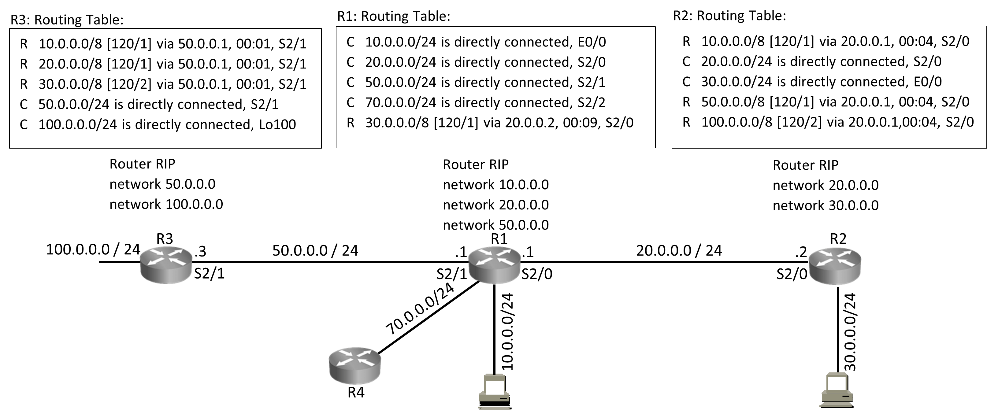
Router RIP < ——- (Starts RIP Routing Process)
network 20.0.0.0
network 30.0.0.0 < ——–(Send update on interfaces where these networks are configured)
Updates include:
- Details of Networks on which routing protocol is operating
- Routes that Routing protocol has received from other neighbors

RIP: OSPF: Higher the Bandwidth.
Criteria = Hops Criteria = Bandwidth Lower the cost.
Metric = Hop Count Metric = Cost Lower the cost, better the path.
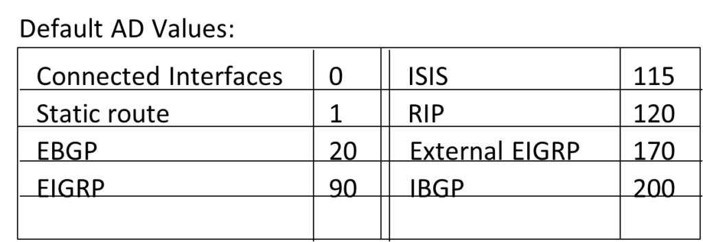
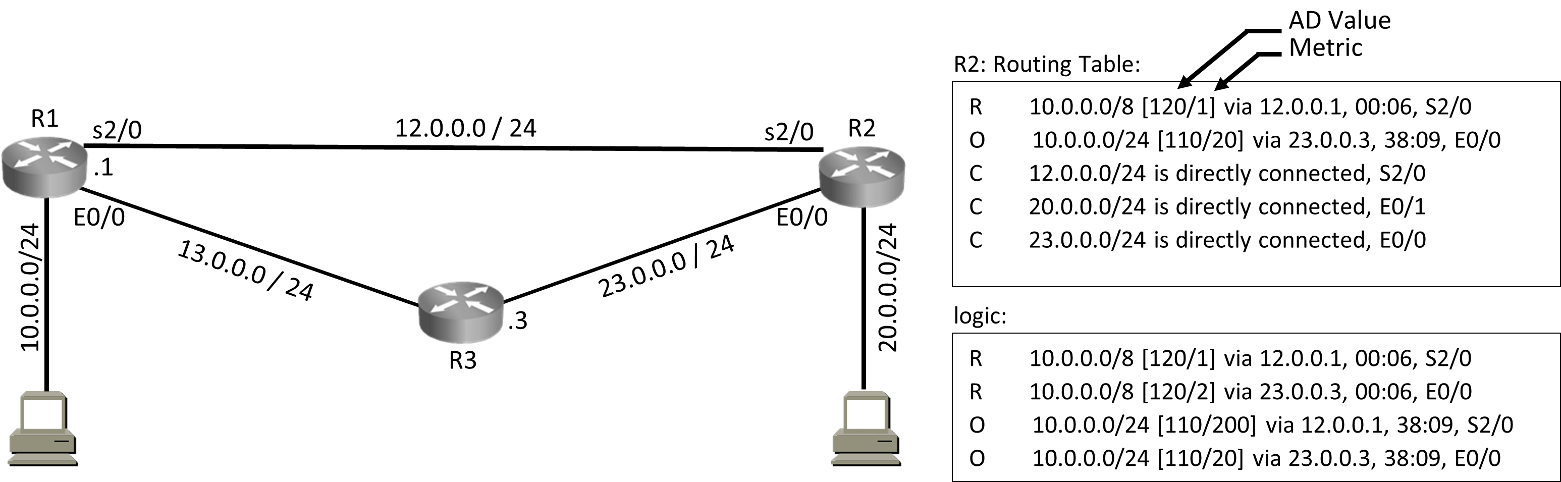
Administrative Distance (AD Value) = Defines Trustworthiness = Routing Protocol with lower AD Value is more trustworthy.
Possible AD Value = 0 – 255
AD Value 0 = Most Trustworthy
AD Value 255 = not Trustworthy (Will be removed from routing table)
RIP AD Value = 120
OSPF AD Value = 110
Punch_Statement:

Load Balancing:

Routing protocols may have multiple best paths (equal metric) to reach a network. Routing protocols will put all best paths to reach a network in routers routing table.
If a Router has multiple best paths to reach a network provided by a routing protocol then router will do load balancing over equal metric paths, this load balancing will be per packet based and routers can do load balancing on up to 32 equal metric paths (IOS dependent).

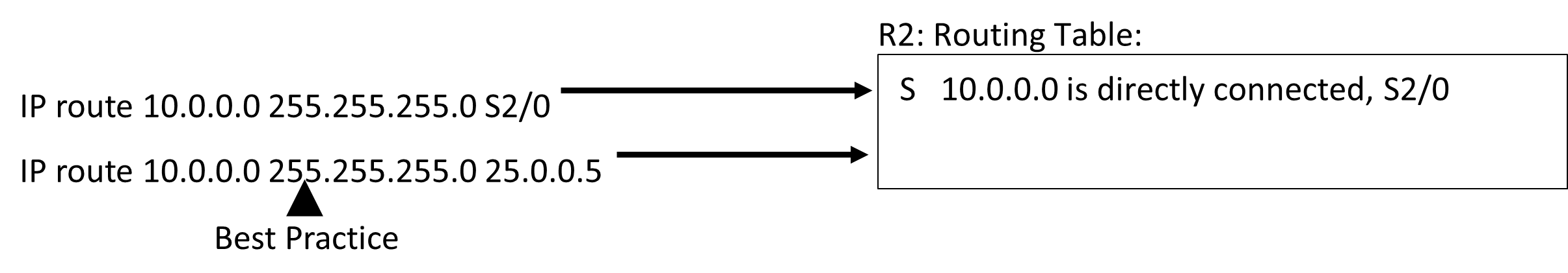
Static Route: Metric
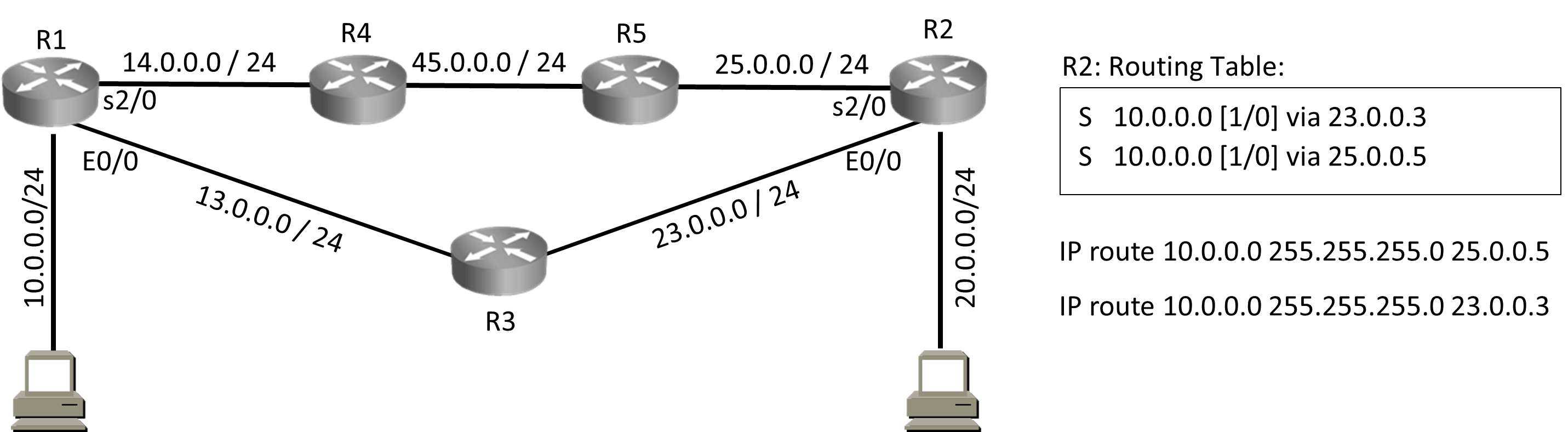

Static Route: Best Path Selection
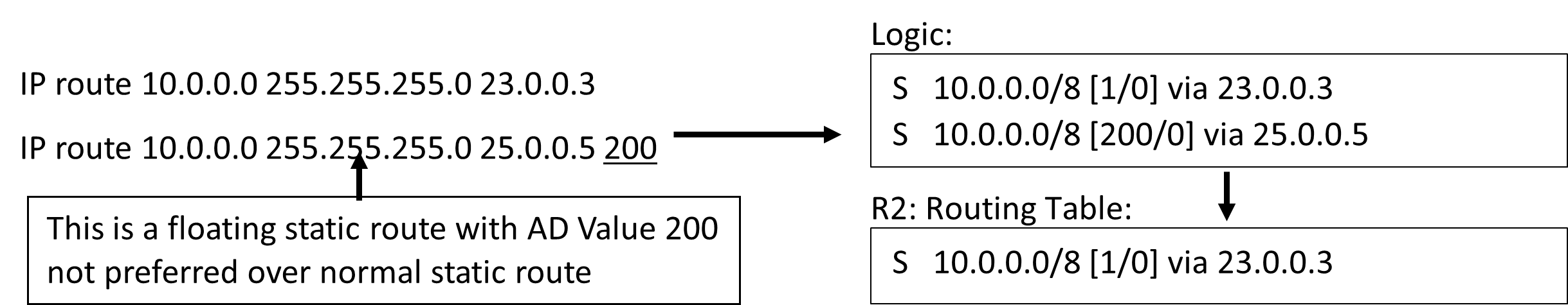
Note: Floating Static route is a static route with AD Value other then 1.

Static Route: AD Value 0

There are multiple ways to configure a static route

Static Route: Permanent
IP route 10.0.0.0 255.255.255.0 23.0.0.3 permanent


Dynamic Routing Protocols: Function of Routing Protocols:


Distance Vector Routing Protocol: are protocols in which:
- Updates are Periodic sent every 30/90sec
- Entire routing table is sent as an update,
- Updates are broadcasted (255.255.255.255)
- Updates are sent to directly connected neighbors only
- D.V. Routers don’t have end-to-end visibility of entire network, directly connected neighbors are the worlds. (Routing by Rumors)
- Because updates are periodic hence convergence is slow. (To converge means to change, convergence means adapting to change)
- Because convergence is slow hence there is possibility of a patch getting created in your network that carries wrong information called as Black-hole.
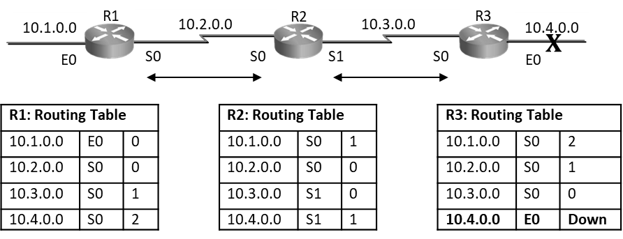
Distance Vector routing protocols are prone to routing loops; as seen below distance vector routers have exchanged routes with their neighbors and routes are seen in routing tables with their respective metrics. After every periodic interval routers will keep exchanging these routes with their directly connected neighbors. Below is steady state routing table.
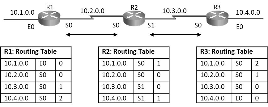
As seen below on R3 router, when E0 port goes down, router will remove the route 10.0.4.0 from its routing table and wait for its periodic timer to come to send this update to its neighbor.
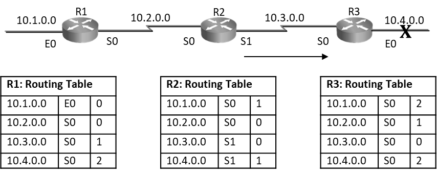
If R2’s Update timer expires before R3 router and it sends routing table to R3 claiming that it can reach 10.4.0.0 at 1hop. Then R3 router will say I don’t know how to reach 10.4.0.0, but if R2 can reach it at 1 hop and I can reach R2 at one hop so via R2 I will reach 10.4.0.0 at 2 hops and hence R3 router will add entry as seen below in diagram, this entry states that R3 can reach 10.4.0.0 via R2 at 2hops. Even though the network is down router is still showing that it can reach it at 2hops. This is a loop situation.
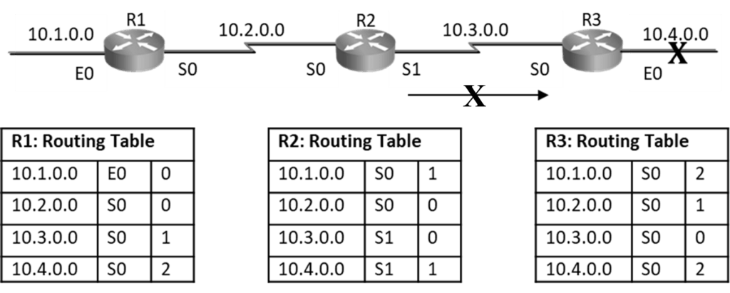
Now when R3 router’s update timer expires and it will send update to R2, its routing table will state that it can reach 10.4.0.0 at 2 hops, in this situation R2 will change its hop count for 10.4.0.0 network to 3hops and similarly R1 will make it 4hops.

Even though the network is down routers will keep exchanging routes with ever increasing hop count. This symptom of counting to infinity indicates routing loop situation.
Multiple solutions were created to overcome routing loops issue:
• Defining a maximum,
• Split Horizon,
• Route Poisoning,
• Poison Reverse,
• Hold-Down Timer,
• Triggered Updates, etc.
Let’s understand some of these solutions.
Defining a Maximum: 16 hops were defined as maximum, possible hops 0 to 15, 16th hop unreachable.

Split horizon: Never send update back in direction from where it came. R3 router originally announced a route to network 10.4.0.0 to R2 router. It makes no sense for R2 router to announce it back to R3
Triggered Update: If there is a topology change, router will send triggered update to its neighbor

Multiple solutions were created to overcome routing loops issue in distance vector routing protocols; solutions like Defining a maximum, Split Horizon, Route Poisoning, Poison Reverse, Hold-Down Timer, Triggered Updates, etc. when these solutions were incorporated to avoid loops now when we see behavior of Distance vector routing protocols it will be different. Now when a link goes down router will immediately send triggered update and at the same time it will also send periodic updates.
Link-State Routing Protocols: are protocols in which
- Updates are triggered they are not periodic
- Updates are incremental, entire routing table is not sent as an update,
- Updates are multicast they are not broadcast.
- Updates are sent to the group and not just connected neighbors.
- L.S. Routers send details like SPF Cost, SPF Tree/Table as part of their update which helps routers build end-to-end visibility of entire network all its paths and their costs in form of topology table (LSDB).
- Convergence is fast because updates are triggered, and routers have E2E visibility of all network, their paths and its costs in form of topology table (LSDB).
Link-State Operations:


Hybrid Routing Protocols :-

- Share attributes of both distance-vector and link-state routing
- Entire operations are pulled from Link State
- Configurational Simplicity is taken from Distance Vector
- EIGRP Belongs to this category
NOTE:
- Distance vector: This approach determines the direction (vector) and distance to any link in the internetwork. Distance means metric: like hop count in the case of RIP. Pure distance vector protocols periodically send complete routing tables to all connected neighbors. In large networks, these routing updates can become enormous, causing significant traffic on the links. The only information that a router knows about a remote network is the distance of metric to reach this network and which interface to use to get there. Distance vector routing protocols do not have end-to-end visibility of network topology. Router has network visibility based on the information received from neighbors.
- Advanced distance vector: The advanced distance vector approach takes best of both link state and the distance vector algorithms. EIGRP is a Cisco proprietary routing protocol that combines the advantages of the link state and the distance vector routing protocols. EIGRP may act like a link-state routing protocol because it uses a Hello protocol to discover neighbors and form neighbor relationships and because only partial updates are sent when a change occurs. However, EIGRP is still based on the key distance vector routing protocol principle that information about rest of the network is learned from directly connected neighbors.
- Link-state: The link-state approach which uses the SPF algorithm, creates an abstraction of the exact topology of the entire internetwork or at least of the partition in which router is situated. A link-state router uses the link-state information to create a topology map and to select the best path to all destination networks in the topology. All the link-state routers use an identical “map” of the network and calculate the shortest paths to reach the destination networks in relation to where they are on this map. Unlike their distance vector counterparts, complete routing tables are not exchanged periodically. Instead, event-based, “triggered” updates containing only specific link-state information are sent. Periodic keepalives that are small and efficient, in the form of hello messages, are exchanged between directly connected neighbors to establish and maintain reachability to its neighbors.
- Classful routing protocols: Classful routing protocols are protocols are protocols in which Masks is not sent as part of update. Routers will automatically summarize at classful network boundary and may lead to sub-optimal forwarding. When classful routing protocols are used all subnets of same major network (Class A, B, or C) must use same subnet mask (may not be default). This will lead to wastage of IP addresses, when we consider point-to-point WAN connections, using a 24-bit network prefix where all that is required is 30-bit prefix. Classful routing protocols are not used anymore and are obsolete now-a-days.
- Classless routing protocols: Classless routing protocols are protocols that send mask as part of update and all issues that were seen in classful routing protocols will automatically get resolved here. Manual summarization may be required to keep the size of routing tables manageable.
Classful Routing Protocol: are protocols in which


NOTES:

OSPF:
- Link State Routing Protocol.
- Classless routing Protocol
- AD-Value = 110
- Protocol no. = 89
- Metric = cost
- Criteria = bandwidth
- Relation is inverse, higher the bandwidth, lower the cost, lower the cost better the path.
- Supports equal-cost multipath
- OSPF does not use TCP/UDP for reliable communication, instead it defines its own Ack packet (OSPF packet Type 5) for reliable communication
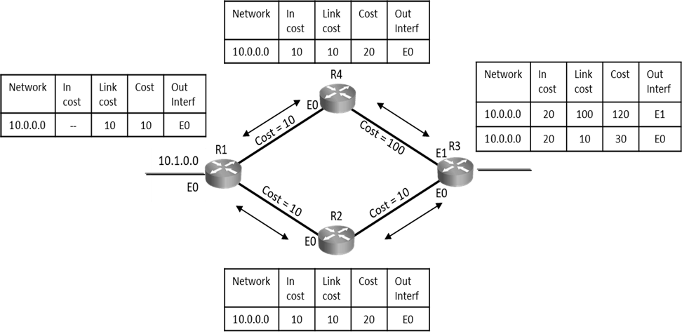
OSPF Cost Calculation:

Note: Default reference bandwidth is 100,000,000 which is equivalent of the bandwidth of Fast ethernet
OSPF Area Concept:
OSPF is a highly scalable routing protocol, created to work on 1000s of routers and handle 1000s of routes. If Your network has 50000 routers and every router has 5 networks and every network has 4 routes, which means all routers will have a million route in its LSDB, OSPF can work on such large-scale networks.
OSPF routers have E2E visibility of entire network all its paths and their costs in form of LSDB.
If all routers have update of all network and its paths, then they will also receive updates when it goes down or comes up. In such huge network there will always be some or the other link failing that will lead to frequent LSA/LSU (Link State Advertisement / Link State Update). Frequent LSA and LSUs will lead to following issues:
- High Bandwidth utilization.
- High Memory utilization.
- High Processor utilization.
- Performance degradation.
Solution: OSPF Area
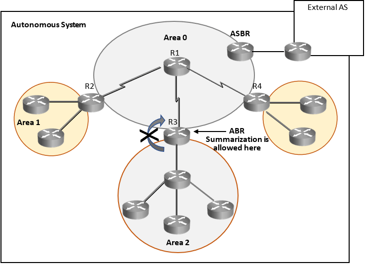
As per OSPF architecture rules, large scale OSPF networks (AS or Domain) should be divided into small areas and LSA/LSU generated in an area should remain within area and these updates should be filtered from going to other areas. Administrators should summarize routes on Area Border Router (ABR), so that LSA/LSU generated within area does not propagate to other areas and LSA/LSU gets controlled.
Now if LSA/LSU does not propagate from one area to other area then area routers may lack visibility of routes in other areas. To overcome this issue OSPF suggests creating Backbone area (Area 0) for inter area communication. Backbone area will be connected to every other area and will have visibility to all area and its routes.
So, what is OSPF area? OSPF area is an administrator defined area, all contiguous networks managed by local administrators should be put in one area. Summarization is not allowed within OSPF area. All routers within an area and Area Border Router(ABR) will receive all LSA / LSU generated within an area directly un-summarized. All routers with in an area will have end to end visibility of all area Internal routes, its paths and their costs in their LSDB (Link State Database).
The other view point is why do we need OSPF area to control LSA/LSU why can’t we just summarize routes on any router to control LSA/LSUs?
Answer is yes, we can do that and use summarization, on any router to control LSA/LSU, but with summarization within an area internal router end to end visibility will be lost, administrators will not learn about link failures of their own network as summarization will filter it.
So, to provide administrators end to end visibility of their own network it was decided to allow summarization only on border routers when updates are being sent to other areas. As it is updates of my link failures going to other areas may be unnecessary.
PUNCH: OSPF area rule is to control frequent LSA/LSU, wherever LSA/LSUs are required put them in one area and filter at ABR using summarization to control LSA/LSUs going to other areas
NOTE: For extra reading:
LSDB: Link State Database is a Topological table that has overall picture of the networks in relation to the routers. It contains LSAs from all routers in that area. Also, as routers in same area share same information hence they have identical topology table.
AS: An AS consists of a collection of networks under a common administration that share common routing strategy. AS can be logically subdivided into multiple areas.
Area: An area is a grouping of contiguous networks

ROUTER-ID (RID):

In OSPF Routers are identified by their Router ID, Router ID is highest IP of Loopback Interface, in absence of loopback interface it is highest IP of active interface when OSPF starts.
Loopback interface is software interface, they are not physically present and are created for testing purposes.
In above example RID of R1 router is 20.0.0.1(highest IP of Loopback). In absence of loopback interface, RID would be 100.0.0.1. as interface with IP 200.0.0.1 is not active (Shutdown).
We can manually configure RID using ‘router-id’ command. It is recommended to use loopback interface as RID. Once RID is selected it remains RID and will not change even if interface with higher IP comes up.
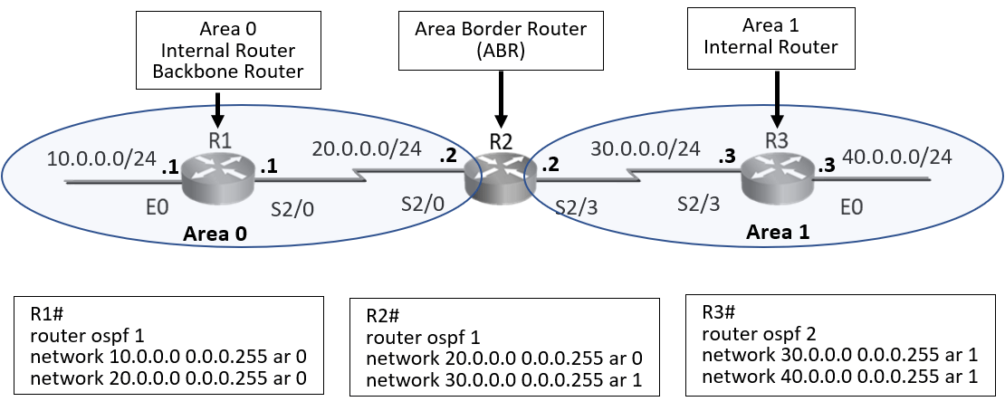
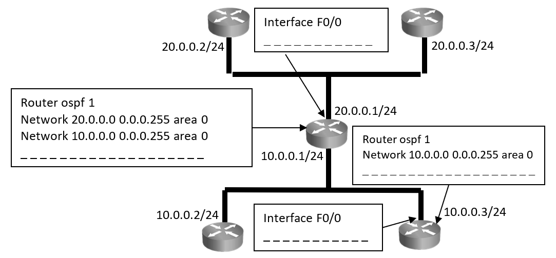
OSPF Configuration:
Task 1: Configure OSPF:
- Process – ID is local to a router, may not match on neighbors.
- Two Directly connected neighbors should be in same area.
- OSPF Areas are on interfaces and borders is on router
Step 1: Configure OSPF on Routers R1, R2, R3 and configure ‘Area’ as seen in the diagram above.
Enter the following command on R1 router.
R1#conf t

R1(config)#router ospf 1

R1(config-router) #network 10.0.0.0 0.0.0.255 area 0

R1(config-router) #network 20.0.0.0 0.0.0.255 area 0

R1(config-router) #end
Enter the following command on R2 router.
R2#conf t

R2(config)#router ospf 1

R2(config-router) #network 20.0.0.0 0.0.0.255 area 0

R2(config-router) #network 30.0.0.0 0.0.0.255 area 1
Enter the following command on R3 router.
R3#conf t

R3(config)#router ospf 2

R3(config-router) #network 30.0.0.0 0.0.0.255 area 1

R3(config-router) #network 40.0.0.0 0.0.0.255 area 1

R3(config-router) #end
Step 2: Examine the IP routing table of all router.

As seen in the routing table routes have exchanged between routers. R1 router has two directly connected router entries for network configured on its own interface. R1 router is area 0 internal router and it has received two routes from its neighbor. These routes are from other area i.e. area1 hence it is reflecting as ‘OIA’ route, that is OSPF interarea route.
R2 router is area border router that belongs to both area 0 and area 1 hence routes learnt from both areas will be considered as area internal route and it will reflect as ‘O’ route in routing table.
Step 3: Exchange routes between different OSPF Processes.
Enter the following command on R2 router to exchange routes between OSPF Processes.


OSPF Multi-area:

- Inter Area communication will happen through Backbone area
NOTE: For extra reading:
In Large networks the connectivity is complex and number of potential path to each destination is large. Therefore, Dijikstra calculations that compares all possible routes can be complex and take a lot of time. This can be resolved by dividing large network in to small areas. The number of routes in an area and the number of LSAs that flood within area are small, which in turn reduces size of topology table for routers in that area. This makes Dijikstra calculation easier and faster. Routers that are inside an area maintain:
- detailed information about the links and
- general or summary information about routers and links in other areas.
However manual summarization is required at the Area Border Router, multi area OSPF architecture helps limiting the flooding of LSA to remain within area. SPF calculation therefore only happens in area where topology change has occurred and LSAs are originated.
Link state routing protocols use two-layer area hierarchy:
Backbone area: The primary function of this OSPF area is to quickly and efficiently move IP packets. Backbone areas interconnect with other OSPF area types. Generally, end users are not found within a backbone area. The backbone area is also called OSPF area 0. Hierarchical networking defines area 0 as the core to which all other areas directly connect.
Normal (Non – backbone) area: Connects users and resources. Regular areas are usually set up along functional or geographical groupings. By default, a regular area does not allow traffic from another area to use its links to reach other areas. All traffic from other areas must cross a transit area such as area 0.
The optimal number of routers per area varies based on factors such as network stability, but Cisco recommends the following guidelines:
- An area should have no more than 50 routers.
- A router should not be in more than 3 areas.
- Any single router should not have more than 60 neighbors.
OSPF architecture must have a contiguous backbone area ‘Area 0’. Area 0 works as core and all other areas connect directly to the backbone area. Backbone area works as transit as all other areas communicate through it. Routers that makeup Area 0 are known as backbone routers. The routers that makeup non-backbone areas are known as internal routers; they have all interfaces only in one area.
ABR: An ABR connects Area 0 to the non-backbone areas. An OSPF ABR has interface in more than one area. ABR has following characteristics.
- It separates LSA flooding zones.
- It becomes the primary point for area address summarization.
- It functions as the source for default routes
- It maintains the LSDB for each area with which it is connected.
ASBR: An ASBR connects any OSPF area to different routing administration. The ASBR is the point where external routes can be introduced into OSPF AS
OSPF on multi-access network:
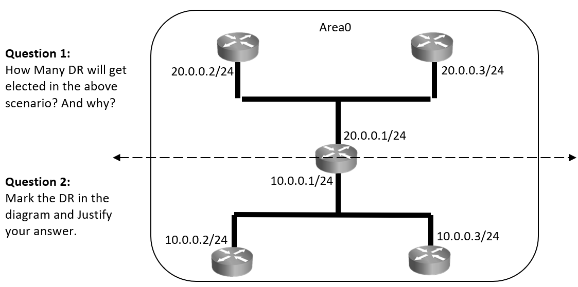
OSPF’s behavior on Multi-access network (Ethernet) is slightly different, on multiaccess network as all routers are neighbor to one another, there may be chaos due to updates and information exchange. To overcome this issue OSPF elects DR (Designated Router) which acts as central exchange point, BDR (Backup Designated Router) that acts as backup to DR and will take role of DR in case DR fails. All other routers will act as DR-other or non-DR routers.
If there is a topology change on any router connected on multi-access network, it will send update to DR and BDR using multicast address 224.0.0.6 (This is the address on which DR/BDR listens).
In turn DR will send this update to DR-other using multicast address 224.0.0.5, This is the address on which DR-other listens. If DR fails to send this update with in stipulated time BDR will become DR and send it, Once BDR becomes DR it remains DR and will not change even if original DR comes up. Now the original DR will act as DR-other because when BDR became DR, some other DR-other was made BDR.
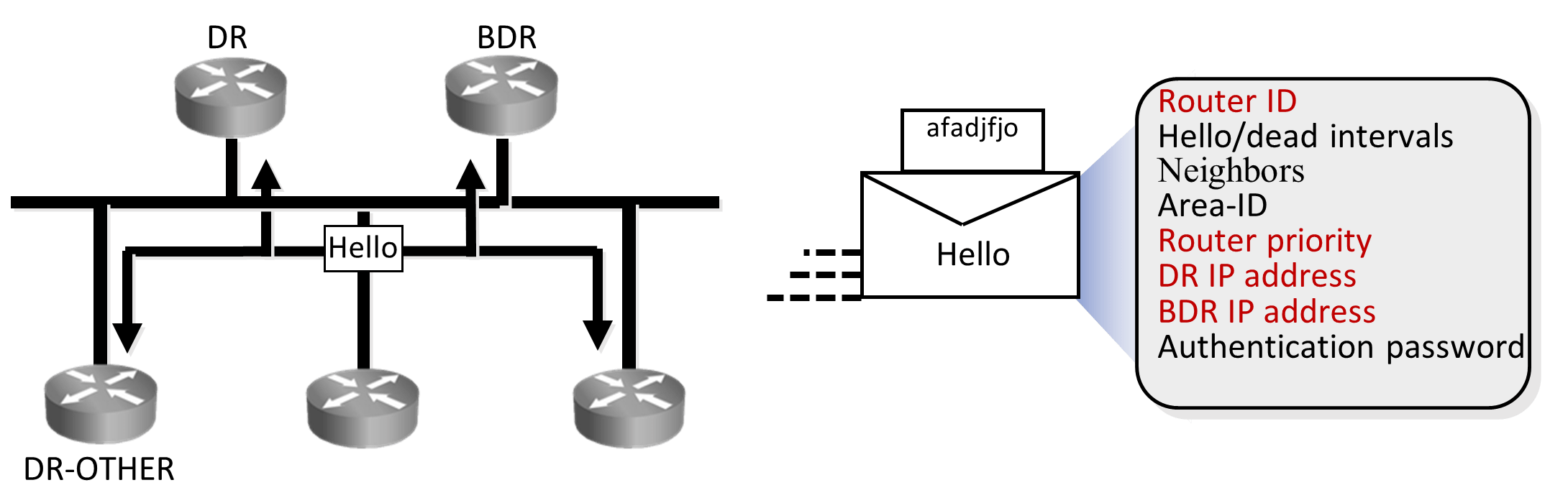
When and how are DR and BDR elected?
Post neighbor formation when routers are in two-way state. DR and BDRs are elected using hellos. As seen in the diagram above, OSPF routers send details like: Router-ID, Router Priority, DR IP and BDR IP as part of hellos that helps in DR/BDR election. Initially all routers will claim themselves to be DR and BDR, but eventually by exchanging these details in hellos appropriate router with higher priority or RID will be elected as DR and BDR.
DR is the router with highest OSPF priority if all routers have same priority then election goes on RID. Administrator can make any router become DR by changing its priority or RID.
OSPF Priority:
- Default priority of all OSPF routers is 1.
- Possible priority is 0 to 255.
- OSPF Priority 0 means forceful DR-other.
- OSPF Priority 255 means forceful DR.
A router with priority set to zero cannot become the DR or BDR. Router with priority 255 is forceful DR.
DR / BDR Manipulation:

Please fill in the command in the above example to make a router become DR by either changing its RID in OSPF process or changing its priority on interface.
OSPF neighbor Adjacency:

Neighbor relationship or adjacency is formed only if following will match on neighbor routers.
- Area ID
- Hello and dead intervals
- Authentication password
- Stub area flag
As seen in the diagram, hellos that are exchanged between OSPF routers to form neighbor relationship carry information like Hello/dead intervals, Area ID and Authentication password required to form adjacency.
Hello interval for multi-access interface Ethernet is 10 Seconds and dead interval is four times hello interval I.e. 40 seconds
NOTE: For extra reading:
All interfaces use multicast address 224.0.0.5 to send periodic hellos.
Neighbors: This field has list of neighbors that have established bidirectional communication. If router RID listed in the neighbor list of received hello that means bidirectional neighbor relationship is formed.
Authentication Data: when authentication is enabled, Neighbors will exchange keys to authenticate each other.
Stub area flag: Administrator can configure an area as stub area. Stub area helps in reducing routing updates by replacing them with a default route. Routers will form adjacency only if they agree on this.
OSPF Neighbor States:
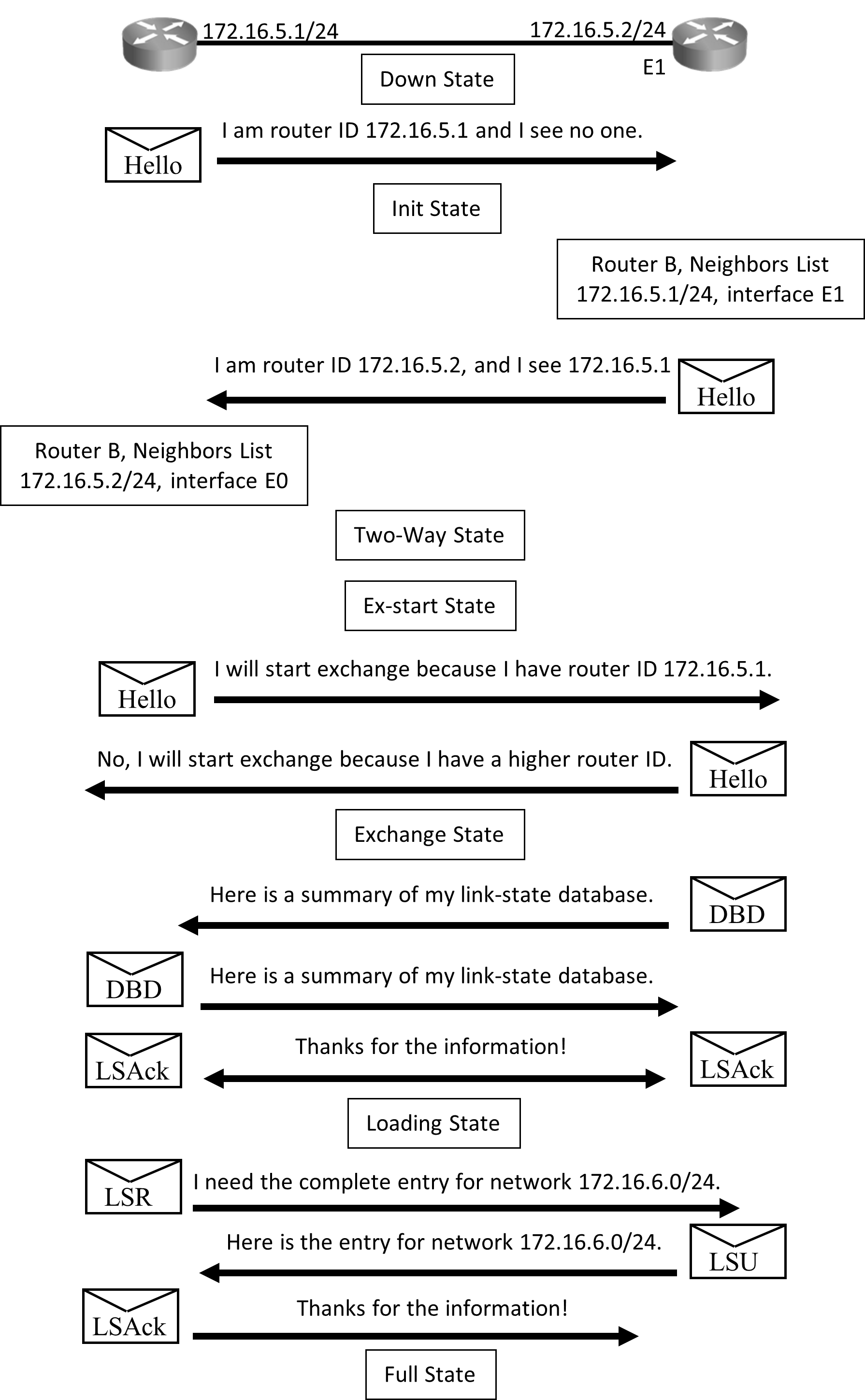
The above diagram illustrates exchange process that takes place between routers when they start:
Initially routers are in DOWN State until they start exchanging information, routers will begin by exchanging hellos. The ‘hellos’ will be sent on directly connected interfaces.
All directly connected routers will receive this hello packet and add the router to their neighbor list and enter in INIT State.
Routers that just received hello packet will send a unicast reply hello packet with latest list of its neighbors.
On receiving this reply, the router will update its neighbor list and enter TWO-WAY state. Routers that have exchanged hello packets will develop a bidirectional communication.
At this stage DR/BDR Election will take place on multi-access network like Ethernet. From here exchange protocol takes over.
Now in the EXSTART State, the DR and BDR establish adjacencies and the router with higher RID will start the exchange process.
In the EXCHANGE State, the primary and subordinate routers exchange one or more DBD packets. If the DBD has more up-to-date link-state entry, then in LOADING state, router sends Link State Request (LSR) to the other router requesting latest entry.
When all requests have been replied, the adjacent routers are considered synchronized and are in the Full State.
All states except Two-way State and Full State are transitory, and routers should not remain in these states for extended period.
Once router enters Full State:
- Exchange of topology table will stop, now routers will send updates only when there is a topology change and that also it will be triggered and incremental only.
- Routers will now run Dijikstra Algorithm on Topology table and select best path and add it to routing table.
- Hello packets that were earlier exchanged to form neighbors are now exchanged as keepalives.
- The router sends the updates periodically as well (every 30 minutes by default).
NOTE: For extra reading:
Four types of update packets are used when building and synchronizing LSDBs:
- DBD packet: A DBD packet is used to describe the network routes of each neighbor.
- LSR packets: After DBD packets are exchanged, the routers request the missing information by using LSR packets.
- LSU packet: All missing information is sent to the neighbors by sending LSU packets that contain different LSAs.
- LSAck packet: Every packet receives an LSAck to ensure a reliable transport and reliable exchange of information.